
Everyone should have a good radio even in the Internet age and nothing beats one that is powered by its own signals.
A crystal radio is nothing more than an inductor and a capacitor in parallel like this:
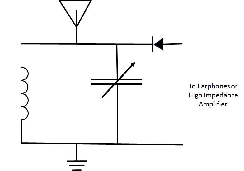
It can receive AM(amplitude modulation) frequencies only. Electrically the signal looks like this:
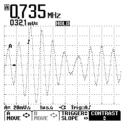
When the antenna is struck by electromagnetic waves(radio) it induces small currents in the circuit. If the radio carrier wave occurs at a resonant frequency the radio is “tuned in” and the signal can be heard on an appropriate listening device. Below is a screen snapshot from my oscilloscope:
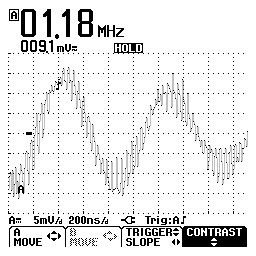
It shows the dominant frequency of about 1MHz and all the other minor signals that are coming in from the antenna.
The only other piece that is required is a rectifier to cut off half of the alternating current signal so that the speaker diaphragm isn’t trying to be pulled in two directions at once(essentially) and goes nowhere. That’s it. That’s all the rocket science there is to a simple radio. The Wikipedia article on crystal radios is more comprehensive but that is it in a nutshell.
When I was in the Army I used to enjoy listening to the BBC on a tabletop shortwave. I decided that for my little set shown above I would wire the inductor so I can receive all of the standard North American AM frequencies plus shortwave bands from around the world.
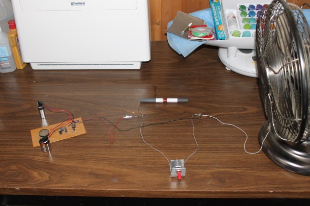
Typically a crystal radio has an inductor coil with a strip of the enamel sanded off so that a wiper can make a connection, changing the inductance value(coil length), and the radio’s received frequency. Unfortunately by exposing the copper we also start corrosion. Instead of this method I am using a six position selector switch to connect to different “taps” on different lengths of a coil with a ferrite core. My radio is currently configured as shown below:
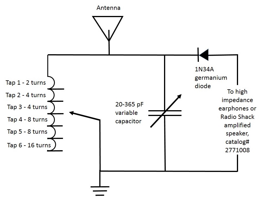
(Click to enlarge)
From my experiments I found that I can receive:
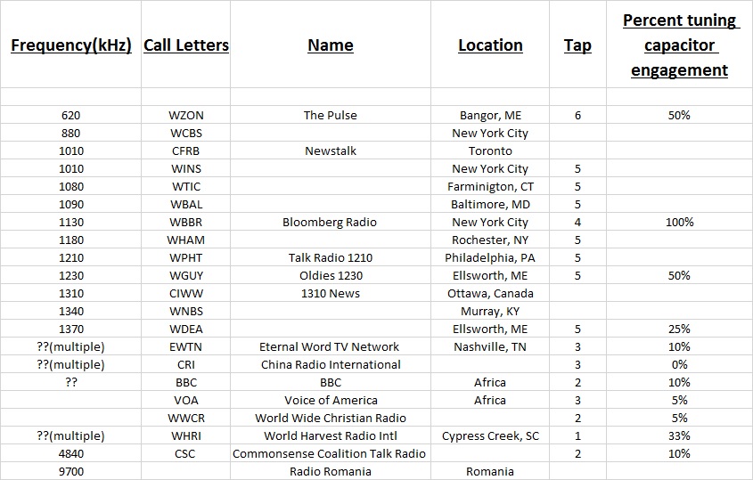
from Ellsworth, Maine. It has also received The Korean Broadcasting Service, Columbia, India, Vietnam, South Africa, Aruba, Alabama, and Tennessee but that was before I was recording my stations. Not bad for a little pile of wires! The antenna is just a fourteen foot long piece of .021OD magnet wire.
In order to figure out if I was missing any frequency bands with my six position selector I ran a test where I tuned in a known sharply defined AM radio station then I disconnected the tuning capacitor wires and measured the capacitance value. I then calculated the inductance the coil had to be producing according to:
Tuned Frequency = 1/(2*PI*(tuner inductance * tuner capacitance)^.5)
I determined that my type 61 1/2″OD X 6″ long ferrite rod and coil produced an inductance of 5.6 microhenries per turn. Therefore my frequency ranges for the various taps should be something like the table below:
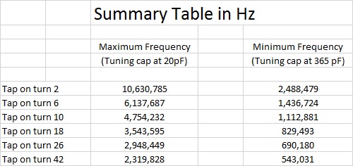
(Click to enlarge)
This does seem to correlate with my experiences. The bottom two taps do seem very similar and bring in the same stations. One range is often clearer than the other for a given station, however.
The one problem that immediately became evident is that when you can receive signals from all over the globe, you need a machine that can be very selective about which signal is being sent to the speaker. This is where an antenna tuner comes in. Think of it as a signal isolator for the radio’s tuner so you aren’t trying to do all the work in one step. Unfortunately tuners don’t work well with short antennas like mine. I will add a tuner as soon as I can run a longer antenna without my wife seeing it.
The other issue is that not all stations are available all the time. At night I can hear New York City which is 472 miles away much better than I can hear my local station thirty miles away. This reverses during day light hours.
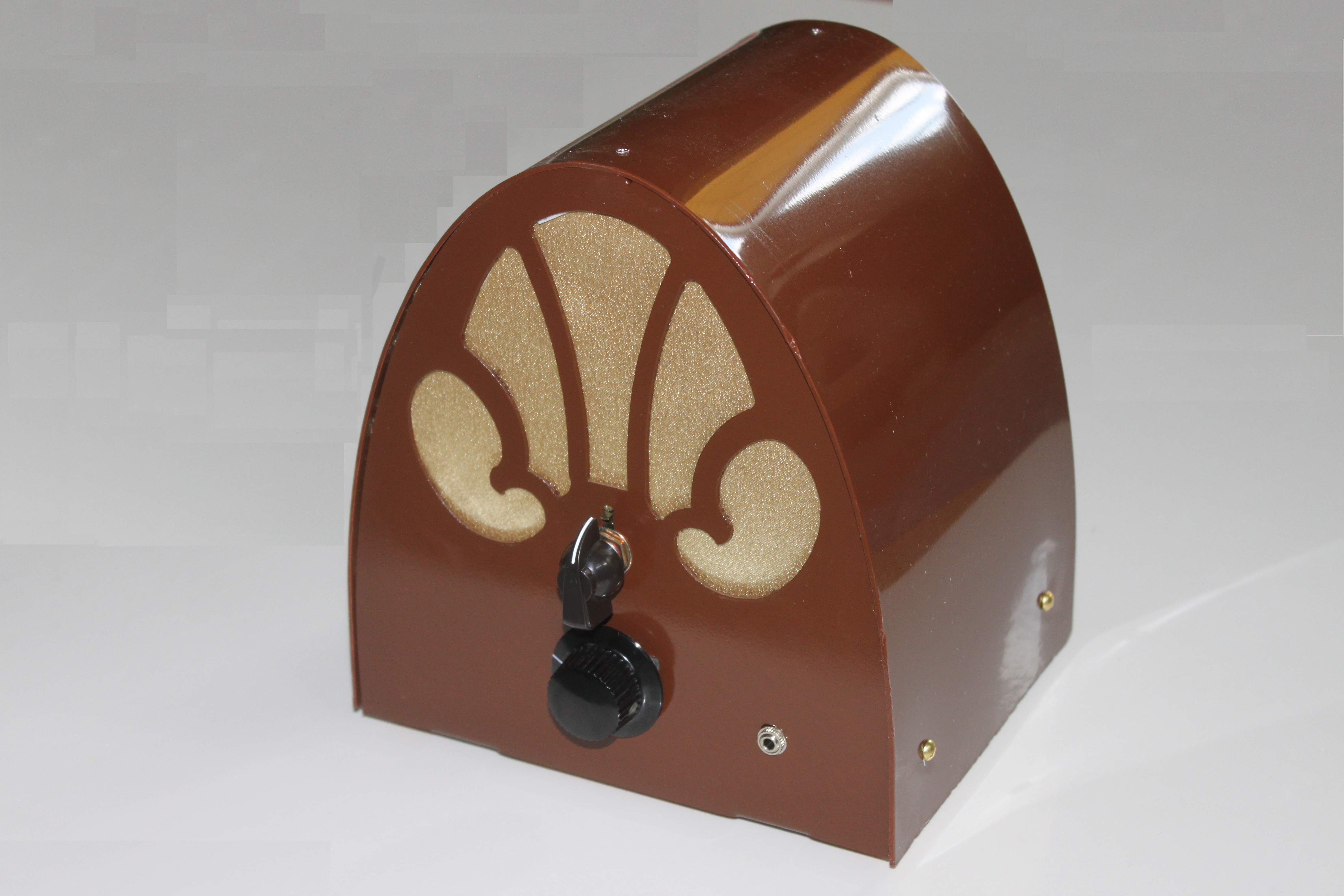
Epic Fail:
Last night I assembled my crystal radio with short wave into this pretty cathedral style chassis:
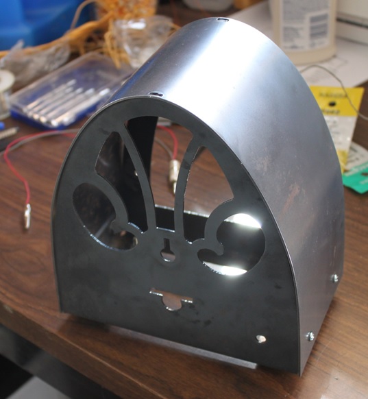
and learned a painful lesson. Crystal radios can’t have conductive housings especially steel ones. The iron absorbs the magnetic field around the coil and kills the reception. I thought that because I was bringing in the signals as current in a wire and keeping the magnetism in a ferrite rod that it wouldn’t matter…..WRONG!!! I tried a test which consisted of inserting the coil while the radio was playing a strong station and it immediately died down to almost nothing. When I retracted the coil, the reception returned. Being a complete geek I refuse to give in so I am going to change to an aluminum front and back panel with a plastic cover. You can’t keep a good geek down!
The Rematch:
Here is the final version of my crystal shortwave:
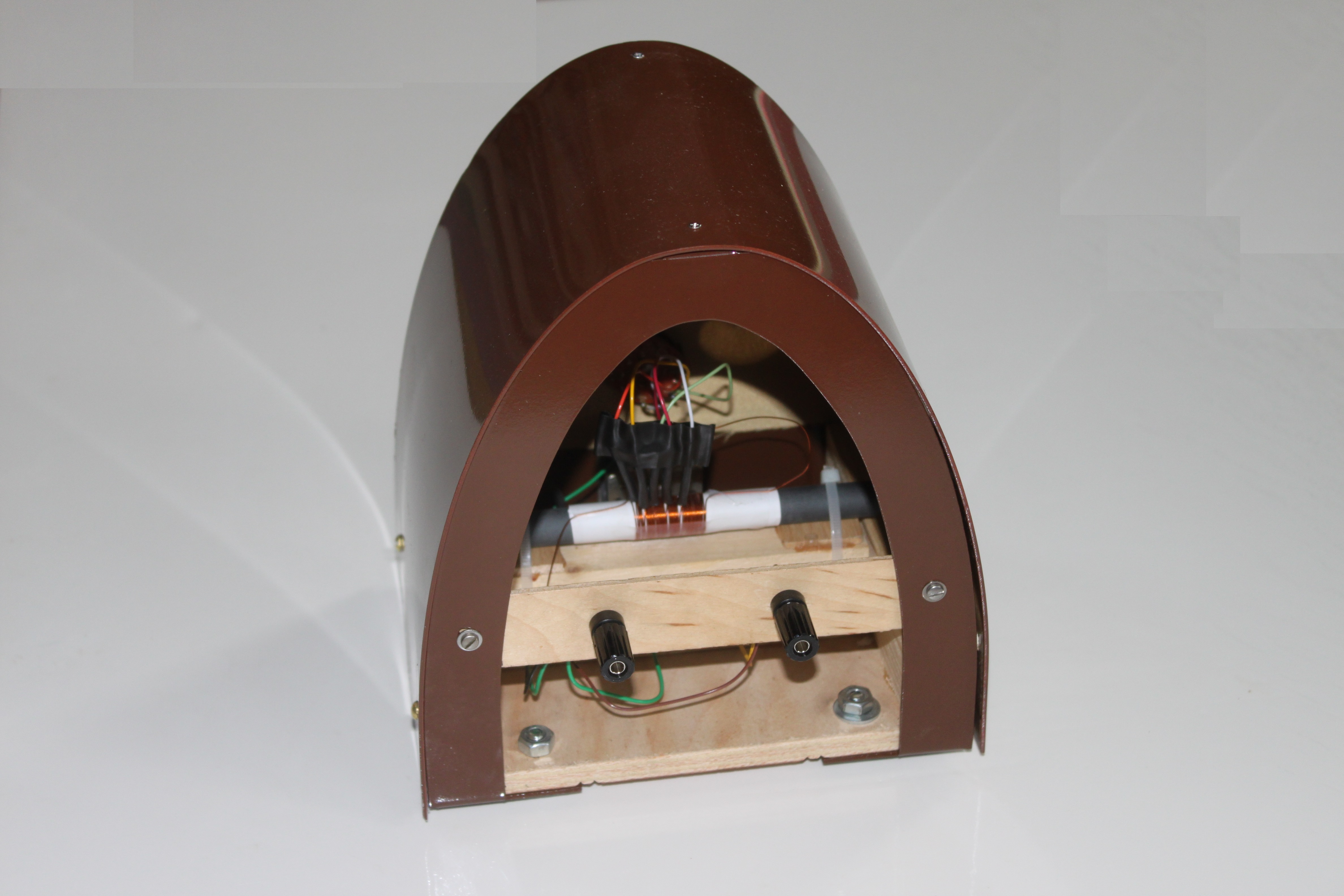
Unfortunately I had to use a steel front and back panel which absorbs some of the signal. The aluminum I tried to cut gave very rough edges and would have needed days of filing and clean up. The bent cover sheet is .060 polystyrene to avoid signal absorption. It is not as sensitive as I would have liked but it is very convenient and the signals that it does receive play solidly instead of drifting in and out. It is a very usable piece of equipment. Even with the signal absorption I am still able to receive New York City which is over four hundred miles away. China Radio International from Cuba does not come in, however. I will probably have to make a high performance radio and a utility radio. At least I am having fun….
Below is a great link to find out who is transmitting and from where:

As far as listening to shortwave broadcasts go back in the 70’s it was a hoot to listen to “The Moscow Mailbag” from the USSR as it was at the time via Radio Moscow. Not sure they do that anymore but given the world situation recently that could change!
very cool, i’ll show this to my son… he’s been interested in this kinda thing for a while.
Hi Arvid..I just added a link to the bottom of the page that should get him all fired up.
Okay, so what do you have for an antenna?
IIRC, I could only get “THE” local radio station, 1440 AM in my home town, Rockford, Ill. with about a 50 antenna 15 feet off the ground on my crystal set, using the Galena crystal/ cat’s whisker diode.
Hi Pete. I have approximately 14ft of .021″ diameter magnet wire as an antenna. It’s in the second story family room running up the wall and laying on the curtain rods going to the other side of the room. I am using a 1N34A diode. My whole inductor only has about 10″ of TOTAL wire on it. There are 4 turns on a .5″ OD ferrite rod. That is probably the biggest difference in our set ups. My tuning cap is a 20-365pF unit. My ground is just the house electrical ground accessed through that metal fan housing in the picture. There is some 60Hz hum but it’s manageable. Hope that helps.
ahhh, too bad about that enclosure because it really looks nice!
Hi Don. I just picked up some .050 aluminum sheet. I am going to burn the same front and back, use a 2X6 wooden base, and sheet the top with .015 lexan. The whole thing will get a coat of mahogany brown. Hopefully it will look as nice as the steel.